


Send the same 0.8 mm wall enclosure to three suppliers and you will get three different answers. One says it cannot be molded at all. One quotes a standard tool price and quietly plans for short shots. One quotes 40% more because, somewhere in the fine print, there is high-speed injection equipment the part actually needs.
The difference is rarely the machine — it is whether the molder treats thin wall injection molding as its own discipline. Thin wall changes the resin you pick, the numbers in your DFM review, and half the components inside the mold. This guide covers the design rules, material choices and tooling changes that decide whether a thin wall project runs cleanly every shift or fights defects from day one.
What Counts as “Thin Wall”?
Most consumer and industrial parts run at 1.5–3 mm nominal wall. “Thin wall” generally means one of the following:
- Absolute thickness: nominal wall of 1.0 mm or less (packaging containers, lids, electronics housings).
- Flow-length-to-wall ratio: the ratio of the longest melt flow path to wall thickness exceeds roughly 100:1, even if the wall itself is 1.2–1.5 mm.
The second definition matters more in practice. A small connector with a 1 mm wall and a 10 mm flow path (10:1) is an easy standard job. A 200 mm long tray at 1.2 mm wall (flow path 250 mm, L/t about 200:1) is a genuine thin wall project, because the melt has to stay liquid across a long, thin channel — and that is where every rule below comes from.
The Number That Decides Everything: Flow Length ÷ Wall Thickness
Before discussing ribs, gates or machines, run one calculation on your part: measure the longest path the melt must travel from the gate to the last corner to fill, and divide it by the nominal wall thickness. That L/t ratio is the single best predictor of whether a thin wall part will fill.
Typical practical limits by material (polygrade-dependent — higher melt flow rate extends the range):
| Material | Practical L/t Limit | Notes |
|---|---|---|
| PP (high MFR, homopolymer) | 250–300:1 | The thin wall workhorse — packaging, lids, tubs |
| PS / HIPS | 200–250:1 | Easy flow, brittle; used where cost dominates |
| ABS | 150–200:1 | Balanced flow and toughness for housings |
| PC / PC-ABS | 100–150:1 | Stiffer and less fluid; needs more gates or thicker walls |
| PA66-GF30 | 80–120:1 | Glass fiber kills flow length fast; freezes quickly |
| POM | 100–150:1 | Narrow processing window; avoid pushing the limit |
The hard rule that follows: if your part exceeds the material’s L/t limit, no amount of machine tonnage will save it. The fix is always one of three things — thicker wall, more gates, or a more fluid resin. This is exactly the trade-off we quantify in our shrinkage and material chart, and it is the first thing we check when a thin wall file arrives for DFM review.
Design Rules That Make Thin Wall Moldable
Thin wall amplifies every classic molding rule. The same geometry that works at 2 mm will produce sink, flash or short shots at 0.8 mm unless it is tightened up:
- Uniform wall, strictly. Hold wall variation within about ±10%. Thick sections next to thin ones sink before you can see it happening, and abrupt transitions freeze at different times, warping the part as it cools.
- Ribs at 50–60% of wall — not more. On a 0.8 mm wall that means rib thickness of 0.4–0.5 mm at the root. A “stronger” 1 mm rib on a 0.8 mm wall is a guaranteed sink mark on the show surface. Thin wall stiffness comes from rib count and geometry, not rib thickness.
- Generous radii. Keep internal radii at 25–50% of wall thickness. Sharp corners are stress risers and flow restrictions — at thin wall they cause both cracks and short shots in the same corner.
- More draft, not less. Counter-intuitive, but thin wall parts eject at higher speed with less material to carry the load. Add 0.5–1° over your standard draft, especially on deep cores; the full logic is in our draft angle guidelines.
- More, larger, balanced gates. Thin wall fills fast, not slowly. Gates must pass a high flow rate in milliseconds without freezing shut — undersized gates shear and burn the material. Multi-gate fills are common, and gate placement decides whether weld lines land where a customer will see them.
- Plan ejection early. A 0.6 mm floor panel cannot survive the ejection force a 2 mm part shrugs off. More and larger ejector pins, striker plates and air assist are designed in from the start — not patched after parts come out warped.
Choosing the Right Material for Thin Wall Parts
Material choice in thin wall molding is less about the polymer family name and more about the melt flow rate (MFR). Two PP grades with the same datasheet properties can behave completely differently if one has MFR 12 and the other MFR 60.
- PP (high MFR, 35–70+): The default for thin wall packaging, lids and containers. Excellent flow, low cost, living-hinge capability. Homopolymer for stiffness; impact copolymer where drop resistance matters.
- ABS (MFR 15–40): The default for thin electronics housings — better stiffness and appearance than PP, fills well at L/t up to ~200:1.
- PC / PC-ABS: When you need impact strength or transparency, accept the shorter flow length: design thicker walls (1.0–1.2 mm), add gates, or both. Full material comparison here.
- PA6 / PA66 (and filled): Tough and heat resistant, but freezes fast — keep L/t conservative and expect more aggressive gate and runner design.
- PPS / LCP: For extreme electronics (0.3–0.5 mm connectors). LCP fills like water but is expensive and abrasive; the mold needs hardened, wear-resistant steel.
One caution: some high-MFR grades trade flow for impact strength and heat resistance. Always confirm the properties you actually need — flow data alone does not qualify a resin for your part.
What Changes Inside the Mold
A thin wall tool is not a standard tool with a thinner core. Expect these differences:
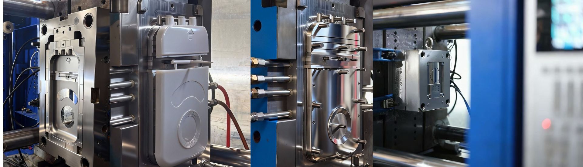
- High-speed, high-pressure injection. Filling must complete before the flow front freezes. Thin wall work typically runs injection pressures of 180–250 MPa against 100–150 MPa for conventional parts, often with accumulator-assisted machines for speed.
- More clamp tonnage. Standard parts use roughly 3–5 tons per square inch of projected area; thin wall typically needs 5–8 t/in² because of the higher cavity pressures. A part that “fits” a 250T machine at conventional settings can flash badly at thin wall pressure.
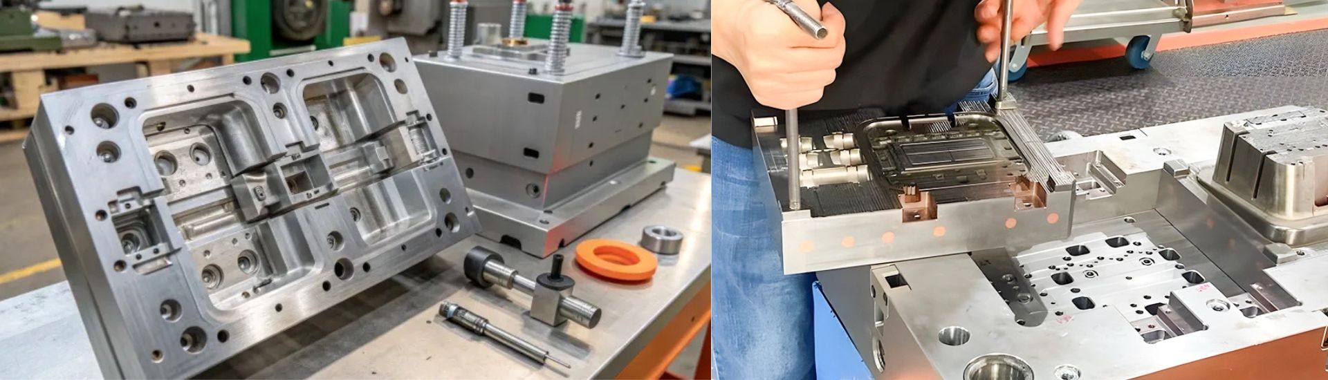
- Aggressive cooling. Cooling dominates the cycle in thin wall — that is the whole economic point. Expect dense cooling channels, beryllium copper or conformal-cooled inserts, and turbulators in deep cores.
- Deep, controlled venting. Fast fills trap air aggressively. Vents of 0.01–0.02 mm at parting lines and dead corners prevent burns and short shots that look mysterious at standard venting depths.
- Hot runners for volume. On multi-cavity packaging tools, a balanced hot runner keeps every cavity at the same pressure drop — which is how 32-cavity lid tools fill evenly at sub-second injection times. The trade-offs are in our hot runner vs cold runner comparison.
- Wear-resistant steel. High injection pressure and filled resins erode gates and parting lines faster. For abrasive grades, that means hardened steels rather than pre-hardened P20 — our steel selection guide maps grades to applications.
Where Thin Wall Projects Fail
After enough thin wall programs, the failure modes repeat. If you want to know whether a supplier has actually molded thin wall before, ask them how they prevent these five:
- Short shots at the far corner — the L/t ratio was never checked, or a high-MFR grade was swapped for a cheaper low-flow one after tooling started.
- Sink over rib and boss roots — someone “beefed up” a rib past 60% of wall on a cosmetic surface.
- Flash around the perimeter — clamp tonnage was calculated with conventional 3–5 t/in² instead of thin wall pressure, or venting got machined too loose.
- Warped panels — unbalanced filling (single gate on a long part) or asymmetric cooling; the part comes out flat at T1 and bows after 24 hours.
- Cycle time quietly doubles — the tool fills fast but cools slowly because the cooling design was treated as an afterthought. The part-cost advantage of thin wall lives and dies on cooling.
When Thin Wall Is — and Isn’t — Worth It
Thin wall pays off when all three conditions hold: volume is high enough to amortize the more expensive tool, material savings matter (wall reduction of even 0.3 mm multiplies across millions of shots), and the part allows it structurally. Food packaging, lids, trays and consumer electronics shells are the classic fits.
Be honest about the cases where it does not pay:
- Low volumes. The tool premium for high-speed injection, hot runner and hardened steel needs volume to pay back.
- Stiffness-critical parts. Bending stiffness scales with the cube of wall thickness — halving the wall cuts stiffness to one-eighth. If the part must carry load or stay dead flat, saving 0.3 mm of resin will cost you a redesign.
- Thick-section functional parts with demanding tolerances — standard wall molding is more forgiving and cheaper to hold.
Quick Reference: Standard vs Thin Wall Molding
| Parameter | Standard Molding | Thin Wall Molding |
|---|---|---|
| Nominal wall | 1.5–3 mm | ≤ 1.0 mm (or L/t > 100:1) |
| Typical L/t limit (PP) | Up to ~250:1 | 250–300:1 with high-MFR grades |
| Injection pressure | 100–150 MPa | 180–250 MPa |
| Clamp factor | 3–5 t/in² | 5–8 t/in² |
| Fill speed | Moderate | Very high (accumulator common) |
| Rib thickness | 50–70% of wall | 50–60% of wall, strictly |
| Cooling design | Standard channels | Dense channels, BeCu / conformal inserts |
Get a DFM Review That Actually Runs the Numbers
The cheapest point to find out that your part exceeds its material’s flow limit is before steel is cut. At D-TOP MOLD, every thin wall inquiry gets a DFM review that includes the L/t calculation, gate strategy, rib and draft verification, and a clamp-tonnage estimate against our press range — so the quote you receive reflects the machine and mold the part actually needs, not a standard tool with thin wall problems hidden inside it.
Send us your 3D model and target wall thickness, and you will have a detailed quote and DFM feedback within 12 hours. If thin wall is not the right call for your part, we will tell you that too — with the math behind it.