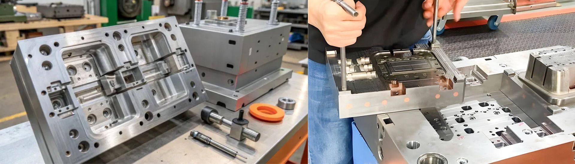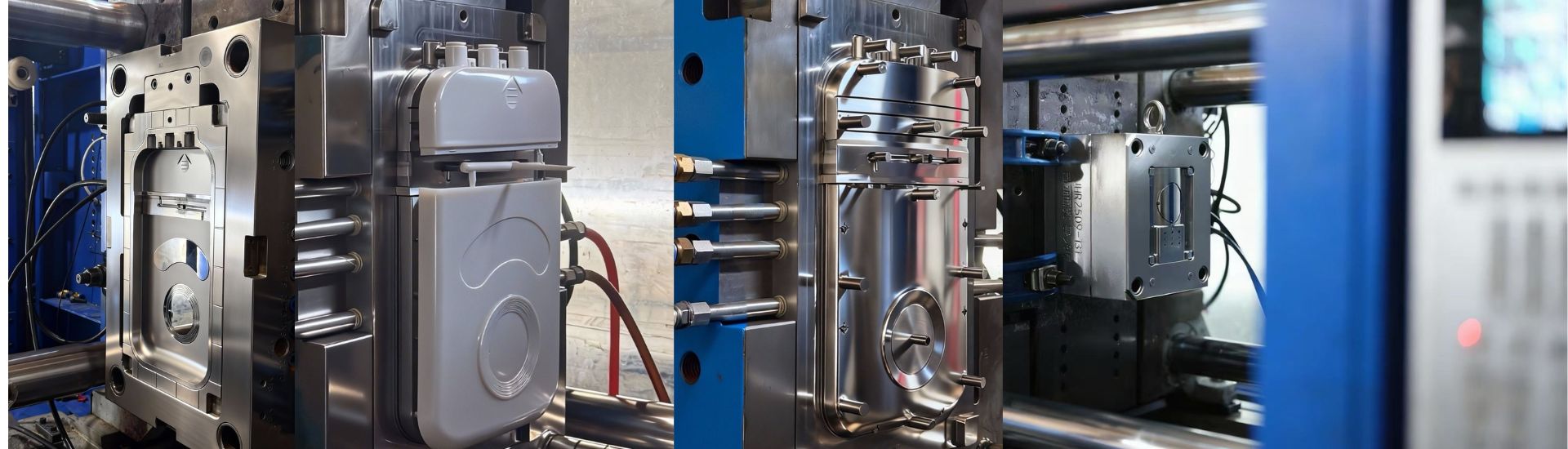


Most Part Problems Are Decided Before Steel Is Cut
“The tooling shop sent back my model with fourteen notes, and eleven of them were about wall thickness. I’d designed the part the way it looked in CAD, not the way it has to be molded.”
That’s the gap most product engineers hit on their first injection-molded part: the geometry that looks fine on screen is full of hidden traps once molten plastic has to flow through it, cool inside it, and release from it. And the three features that decide whether a part molds cleanly or fights you for its whole life are the ones in this article — wall thickness, ribs, and bosses.
This guide gives you the concrete design rules for all three: the numbers that matter, the ratios to respect, and the common mistakes that turn a “cheap” part into an expensive mold. It’s written for engineers and buyers who need to get a part moldable before they send it out for quote.
Wall Thickness: The Single Most Important Number
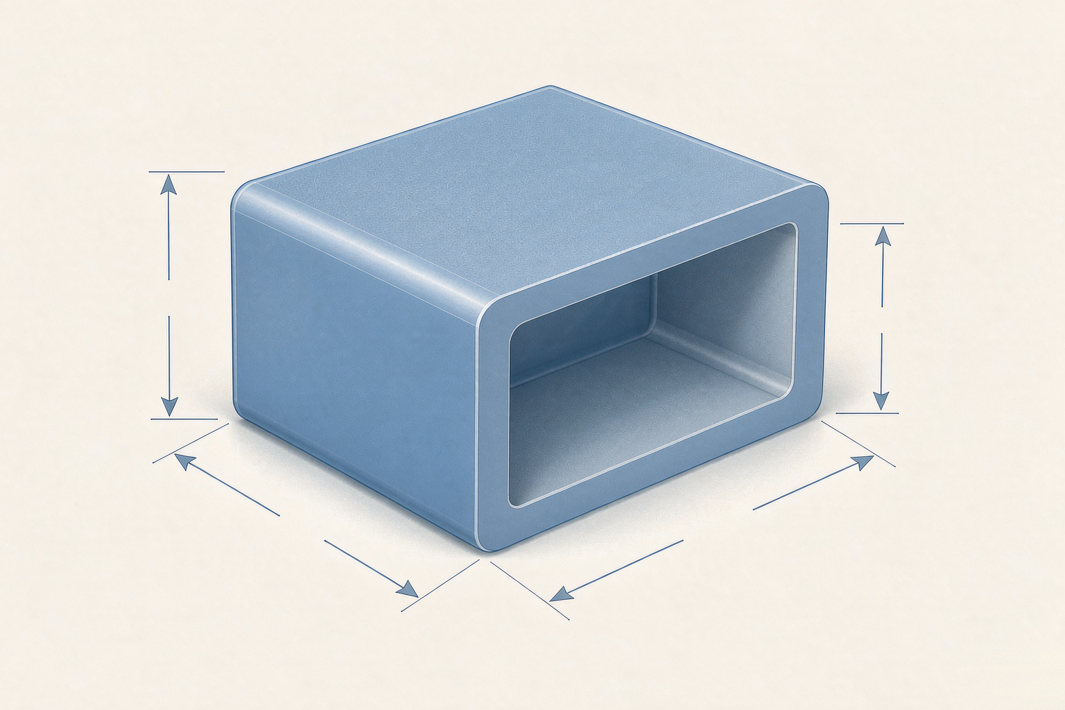
Wall thickness is the master variable in injection molding. It drives how the plastic fills the cavity, how long the part takes to cool, how much it shrinks and warps, and how much material you pay for. Get the wall wrong and everything downstream suffers — sink marks, voids, warpage, long cycle times, and a mold that needs constant adjustment.
The goal is a wall that is as uniform as possible, because plastic cools from the outside in, and a wall that changes thickness cools unevenly. The thick area stays molten longer, shrinks more, and pulls the surrounding material into a sink mark or a warp.
How Thick Should the Wall Be? Material-by-Material
The ideal wall thickness depends on the resin, because each material has a different flow length and shrinkage behavior. Here’s a practical starting range for the most common engineering resins:
| Material | Typical wall range (mm) | Notes |
|---|---|---|
| ABS | 1.0 – 3.5 | Very forgiving; great all-rounder |
| Polypropylene (PP) | 0.8 – 3.0 | Flows easily, good for thin walls and living hinges |
| Polycarbonate (PC) | 1.0 – 3.5 | Needs generous draft and uniform walls; stress-sensitive |
| PA (Nylon 6 / 6,6) | 0.8 – 3.0 | Thin walls flow well; watch moisture and shrinkage |
| POM (Acetal) | 0.8 – 3.0 | Stiff and self-lubricating; sinks easily if too thick |
| PC/ABS blend | 1.0 – 3.5 | Balanced flow and impact; popular for housings |
These are starting points, not hard limits — a tiny connector pin can be thinner, and a large structural panel can be thicker with care. The deeper point is to keep the wall consistent. For the full picture on how each resin behaves as it cools, our material selection guide and shrinkage rate chart walk through each family in detail.
The Uniformity Rule: Why Thick-to-Thin Transitions Fail
The single most common design flaw we flag in DFM reviews is a part that’s mostly 2 mm but jumps to 6 mm at a corner or a mount. That transition is where sink marks and warpage are born, because the thick section cools slower than everything around it.
When you can’t avoid a thickness change, the rule is simple: transition gradually, not in a step. Taper the change over a distance of at least three times the thickness difference, or use a smooth radius. A gentle ramp lets the material cool at a more even rate and dramatically reduces sink and internal stress.
If a thick section is functionally unavoidable — a mounting pad, a threaded area, or a structural boss — the fix is usually to core it out rather than leave it solid. A hollow boss with a controlled wall thickness molds better and sinks less than a solid block of the same size.
Ribs: Stiffness Without the Weight (or the Sink)
Ribs are how you add stiffness to a part without thickening the whole wall — and that’s the key insight, because thickening the wall is the expensive, sink-prone way to get stiffness. A well-designed rib gives you most of the rigidity of a thicker wall at a fraction of the material and cooling time.
But ribs only work if you respect one ratio: the rib thickness must stay below the nominal wall thickness. Specifically, a rib should be no more than about 50–60% of the wall thickness at its base. Why? Because a rib that’s as thick as the wall (or thicker) creates a thick cross-section at the junction, and that junction will sink — you’ll see a visible depression on the opposite surface, right where the rib meets the wall.
The other numbers that matter for ribs:
- Height: keep a rib no taller than about 3× the wall thickness. Taller than that and it becomes hard to fill and hard to cool.
- Draft: give every rib 0.5°–1.5° of draft per side so it releases cleanly from the tool.
- Spacing: if you need multiple ribs, space them at least 2× the wall thickness apart so the cooling between them stays even.
- Root radius: a small radius at the base of the rib (roughly 0.25–0.5× the wall) reduces stress concentration and improves flow.
Ribs are also where draft angle matters most, because a tall, straight-walled rib is exactly what hangs up in the tool. Our draft angle guide covers the exact angles to use per material.
Bosses: The Feature That Anchors Every Fastener
A boss is the cylindrical projection that receives a screw, a pin, or a press-fit insert. Almost every molded part has them, and almost every new engineer designs them too thick — because a boss has to hold a fastener, the instinct is to make it beefy. That instinct creates sink marks on the opposite face of the part.
The rules for a clean boss:
- Keep the boss wall thin. Like a rib, the boss wall should be about 50–60% of the nominal wall thickness. The stiffness comes from the geometry, not from the plastic volume.
- Support it with gussets. A free-standing boss is weak and prone to breaking off. Add gusset ribs (again at the 50–60% thickness rule) connecting the boss to the wall or base.
- Core it out. A solid boss is a sink magnet. The hole through the center is what keeps the wall thickness uniform and the boss moldable.
- Watch the depth-to-diameter ratio. For a self-tapping screw boss, the hole depth is typically 2–3× the screw diameter; deeper than that and you run into fill and ejection problems.
- Add a small radius at the base. A sharp corner at the boss-to-wall junction concentrates stress and creates a crack initiation point.
If the boss needs to take a metal thread, that’s a job for an insert rather than a self-tapping screw in raw plastic — and inserts bring their own design considerations, which deserve their own look.
The Design Rules That Make a Part Moldable
Beyond walls, ribs, and bosses, there are a handful of rules that separate a moldable part from a redesign waiting to happen. We’ve already written the full checklist, so here’s the short version of the ones that interact with wall thickness:
- Uniform wall is king. This is the rule the others exist to protect.
- Core out thick sections. Whenever you see a solid block, ask whether it can be hollowed with a controlled wall.
- Round the corners. Sharp internal corners create stress risers and flow restrictions; a radius of 0.5× the wall thickness is a good default.
- Add draft everywhere. Vertical walls need draft to release — typically 0.5°–2° depending on material and texture.
- Avoid undercuts unless you mean to. An undercut means a slide, a lifter, or a secondary operation — all of which add tooling cost.
The complete version of these, with the reasoning behind each one, is in our DFM checklist. If you’re about to send a part for quote, that’s the article to read first.
The Mistakes That Turn a Cheap Part into an Expensive Mold
Here’s what we actually see in DFM reviews, ranked by how often they cause problems:
1. Non-uniform walls. The 2 mm-to-6 mm jump. It causes sink, warp, and cycle-time drag, and it’s the first thing a good molder will flag.
2. Ribs and bosses designed full-thickness. The “make it stronger by making it thicker” instinct. It reads as stiffness in CAD and shows up as sink marks on the molded part.
3. Missing draft. A part with zero draft on vertical walls will still mold — slowly, painfully, and with ejection marks and stress. Adding draft later is a redesign, not a tweak.
4. Sharp internal corners. They concentrate stress and can crack under load or during ejection, and they restrict material flow.
5. Ignoring the gate location. Wall thickness and gate position are a system: the gate has to be placed where the thickest flow path can fill evenly. Design the part and the gate together, not separately.
Each of these, left unaddressed, produces defects that are visible and expensive. If you want to recognize them before they cost you a batch, our guide to the 12 most common defects connects every symptom back to its design cause.
How to Send a Part That Quotes Cleanly
When you send a part out for injection molding, the quality of your 3D file and your design decisions directly determine the quality of the quote — and the tool. Here’s what to include so you get a useful answer back, not a round of clarifying emails:
- A STEP or IGES 3D file (not just a 2D drawing — the molder needs the solid geometry)
- The resin, and if you can, the specific grade and fill
- The expected annual volume (this drives cavity count and tooling strategy)
- Which surfaces are cosmetic and which are functional
- Any critical tolerances, marked on the drawing
The single best thing you can do before quoting is run a quick self-check against the rules above — uniform wall, ribs and bosses at 50–60% thickness, draft on vertical faces, rounded corners. A part that already respects these rules quotes faster, molds cleaner, and costs less over its life.
Get Your Part Reviewed Before You Cut Steel
Wall thickness, ribs, and bosses aren’t glamorous design topics — but they’re where injection-molded parts either succeed quietly or fail expensively. The good news is that all of it is checkable in a few minutes with the right eye on the model.
That’s what a DFM review is for. Send us your STEP file and tell us what the part does — we’ll flag every wall-thickness, rib, and boss issue before any steel is cut, suggest the fixes that cost nothing at this stage, and give you a quote within 12 hours. It’s the cheapest insurance you can buy on a mold, and it costs you nothing to ask. Contact D-TOP MOLD and send the file — we’ll take it from there.