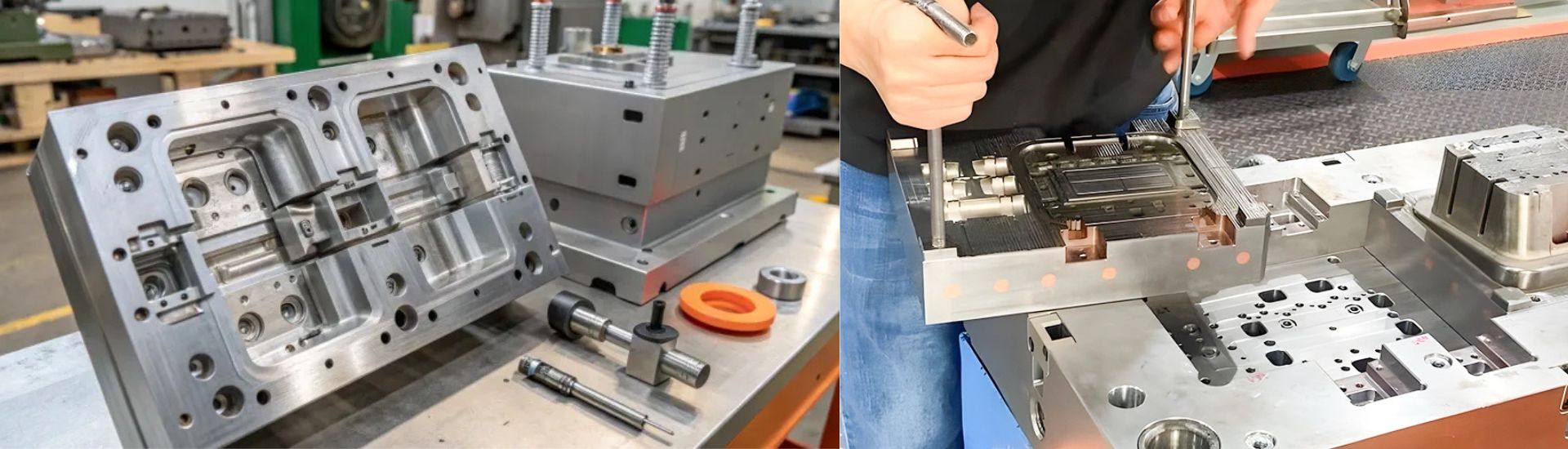


Ask a molder to build a mold cavity at exactly 100.00 mm for a polypropylene part, and the parts that come out will measure closer to 98 mm. That 2% difference is mold shrinkage — and it is one of the first numbers a toolmaker calculates, because every dimension on your drawing depends on it. Specify the wrong shrinkage rate and the mold will produce beautiful parts that do not fit your assembly.
This guide explains what plastic shrinkage rates mean, why they differ so much between resins, and how they are compensated in mold design — with a practical chart by material you can use when reviewing quotes and drawings.
What “Shrinkage” Actually Means in Injection Molding
Mold shrinkage is the difference between the size of the mold cavity and the size of the molded part after it has cooled to room temperature, expressed as a percentage:
Shrinkage (%) = (Cavity dimension − Part dimension) / Cavity dimension × 100
If a cavity is 100 mm and the part measures 99.5 mm after cooling, the material shrank 0.5%. The moldmaker then makes the cavity oversize by that amount — 100.5 mm of steel for a 100 mm part — so the finished parts land on your nominal dimension.
Shrinkage is normally measured on standardized test bars (ISO 294-4 or ASTM D955) after they have cooled for a fixed time, typically 24 to 48 hours after molding. That waiting period matters, and it is a common source of measurement disputes: parts keep moving for hours after they leave the press.
Why Plastic Parts Shrink: Packing, Cooling and Crystallinity
Three mechanisms drive shrinkage, and they stack:
- Thermal contraction. Melt is injected at 200–300 °C and cools to room temperature. Like any solid, plastic contracts as it cools.
- Packing pressure. While the cavity is full of pressurized melt, the screw keeps pushing material in to replace what is contracting. Parts that are well packed shrink less; parts with inadequate packing shrink more and show sink marks and voids — two of the most common injection molding defects.
- Crystallization. Semi-crystalline resins (PP, PE, PA, POM, PBT) form ordered crystal regions as they cool. Crystals pack the molecules far tighter than the amorphous melt, so these materials lose several percent of volume on crystallization alone. Amorphous resins (ABS, PC, PS, PMMA) never organize like that, so they shrink much less.
This is why the material family — not the brand — is the biggest single factor in the shrinkage number on your quote.
Mold Shrinkage vs Post-Mold Shrinkage
Not all shrinkage happens in the mold. Buyers should understand the distinction:
- Mold shrinkage is the dimensional change measured shortly after molding. The moldmaker compensates for this by cutting the cavity oversize.
- Post-mold shrinkage is the additional movement that happens over the following hours, days or weeks — driven by continued cooling, stress relaxation, and moisture uptake. Nylon is the classic example: dry-as-molded PA6 shrinks one amount, then absorbs moisture and grows, partly canceling the shrinkage.
For tight-tolerance parts, ask the molder whether the quoted dimensions are measured at 24 hours or after conditioning. Comparing a part measured fresh off the press against a drawing that assumes conditioned nylon is a guaranteed argument.
Plastic Shrinkage Rates Chart by Material
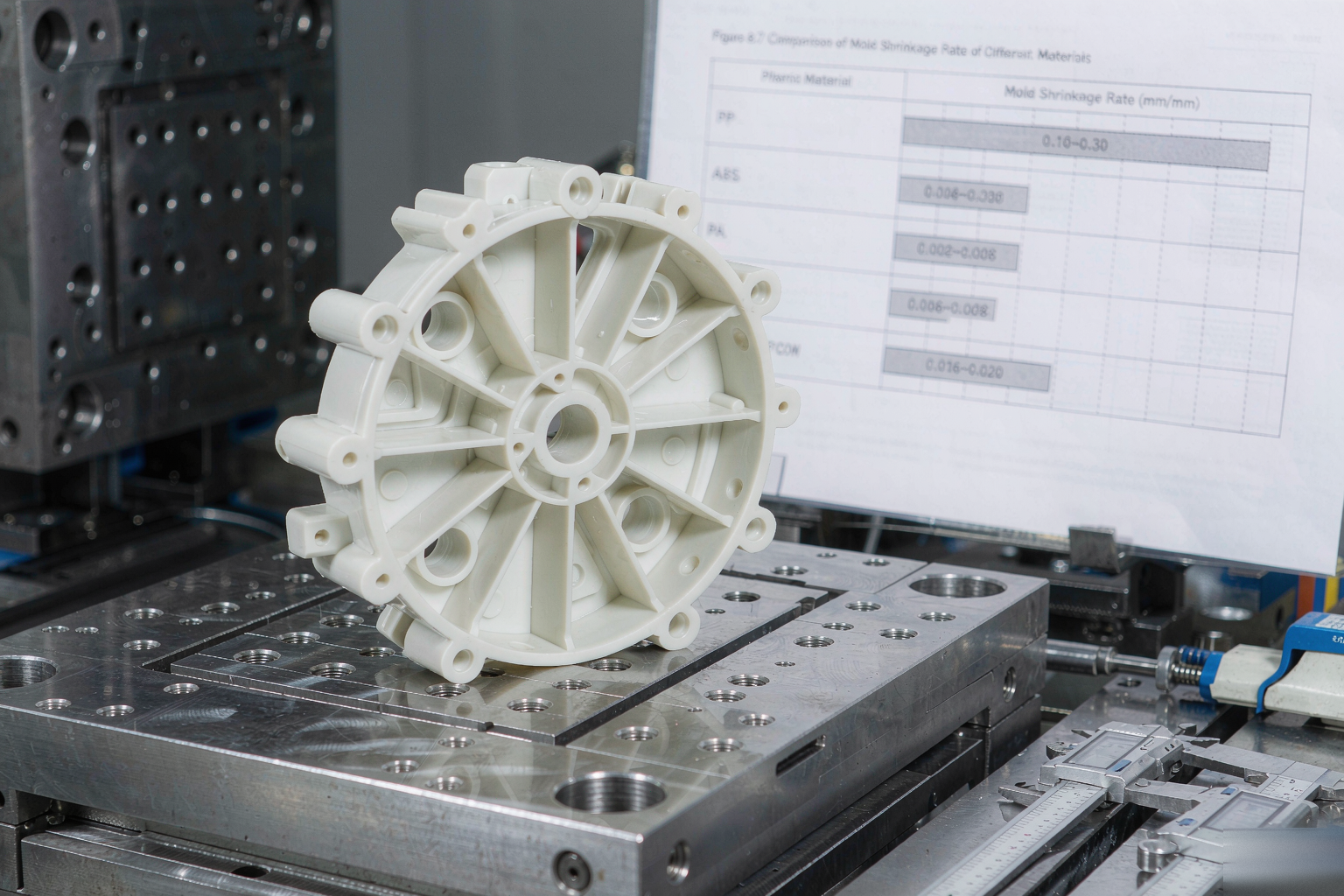
The table below lists typical mold shrinkage ranges for the resins most often used in injection molding. Values are a starting point for tool design — the exact number for a given part depends on wall thickness, flow direction, packing and processing conditions, so always confirm with the material supplier’s datasheet and the molder’s moldflow analysis.
| Material | Typical Mold Shrinkage (%) | Notes |
|---|---|---|
| PP (unfilled homo/copolymer) | 1.2 – 2.5 | Semi-crystalline; direction-dependent, thick walls shrink more |
| HDPE | 1.5 – 3.0 | Among the highest of commodity resins |
| LDPE | 1.5 – 3.5 | Soft, high shrinkage, wide spread |
| ABS | 0.4 – 0.7 | Amorphous; predictable and uniform |
| PS / HIPS | 0.4 – 0.7 | Amorphous; stable |
| PC | 0.5 – 0.7 | Amorphous; good for tight tolerances |
| PC/ABS blend | 0.5 – 0.7 | Behaves like its amorphous parents |
| PA6 (unfilled, dry) | 0.8 – 1.5 | Grows again with moisture conditioning |
| PA66 (unfilled, dry) | 1.0 – 2.0 | Higher crystallinity than PA6 |
| PA66-GF30 | 0.2 – 0.5 | Anisotropic: low in flow, higher cross-flow |
| POM (acetal) | 1.8 – 2.5 | High crystallinity; excellent stability after settling |
| PBT (unfilled) | 1.2 – 2.0 | Fast-crystallizing |
| PBT-GF30 | 0.2 – 0.8 | Strong anisotropy |
| PMMA (acrylic) | 0.3 – 0.8 | Amorphous; optically clear grades |
| TPE / TPU | 1.0 – 2.5 | Varies widely with hardness |
| PPS-GF40 | 0.1 – 0.3 | High-temperature, glass-filled |
| LCP | 0.0 – 0.3 | Very low, but strongly directional |
Two patterns are worth memorizing: amorphous resins cluster around 0.4–0.8%, while unfilled semi-crystalline resins sit between roughly 1% and 3%. Glass filling pulls the crystalline family down into amorphous territory.
Amorphous vs Semi-Crystalline: Why the Ranges Differ
The ranges above are not arbitrary — they follow from polymer structure.
Amorphous resins (ABS, PC, PS, PMMA, PC/ABS) have randomly arranged molecular chains. Cooling changes their density modestly and gradually, so shrinkage is low, consistent, and roughly equal in all directions. That is why amorphous materials are the default choice for tight-tolerance housings and optical parts.
Semi-crystalline resins (PP, PE, PA, POM, PBT) crystallize as they cool, and crystal regions are denser than amorphous regions. More crystallinity means more shrinkage. The catch: crystallinity depends on how fast the part cools and how it is packed, so the same resin can shrink 1.2% in a thin, fast-cooling section and 2.5% in a thick, slow-cooling boss. This thickness sensitivity is also why sink marks appear over ribs and bosses in exactly these materials.
Which resin fits your part is a bigger conversation — our plastic material selection guide covers the trade-offs between PP, ABS, PC, PA and POM in detail.
How Fillers and Glass Fiber Cut Shrinkage
Fillers barely shrink at all compared with the resin around them, so every percent of filler dilutes the resin’s shrinkage:
- Mineral fillers (talc, calcium carbonate) reduce shrinkage moderately and keep it fairly isotropic.
- Glass fiber reduces shrinkage dramatically — PA66-GF30 shrinks around 0.2–0.5% instead of 1.0–2.0% unfilled — but it makes shrinkage anisotropic. Fibers align with the flow direction during filling, so the part shrinks less along the flow and more across it. A rectangular part can come out measurably non-square.
Anisotropic shrinkage is one of the hardest problems in tool sizing. It is predicted with moldflow analysis and verified with T1 trials, which is exactly why experienced toolmakers budget for a measurement-and-steel-adjustment loop on glass-filled projects instead of promising perfect steel on the first cut.
How Shrinkage Is Compensated in Mold Design
Compensation is a design-stage activity, not a trial-and-error one. The workflow looks like this:
- Agree the material and grade first. Shrinkage is specified per grade, not per family. A 30% glass-filled grade and an unfilled grade of the same resin can differ by 1.5 full points.
- Run moldflow analysis. Filling and packing simulation predicts local, directional shrinkage across the part — not just one average number — and flags areas at risk of sink and warpage. See our DFM checklist for where this fits in the design-for-manufacturing review.
- Scale the cavity in CAD. The toolmaker applies the shrinkage factor to cavity and core dimensions. Critical dimensions get scaled individually; uniform “scale everything” scaling is only safe for simple, isotropic parts.
- Leave steel to adjust. Where a dimension is uncertain, the cutter leaves the core slightly large so it can be cut down after T1 — adding steel back is far more expensive than taking it off.
- Measure T1 parts at the agreed time. Full dimensional report, measured at the same conditioning the drawing specifies, then adjust the steel once if needed.
What Shrinkage Means for Your Tolerances
Shrinkage variability sets a floor on how tight your tolerances can realistically be. Standards such as DIN 16901 / ISO 20457 group plastics into tolerance classes precisely because a ±0.05 mm tolerance is routine on ABS and fantasy on unfilled PP.
Practical guidance:
- Amorphous, unfilled: tight tolerances are achievable; small critical features can hold ±0.05–0.1 mm on well-controlled tools.
- Semi-crystalline, unfilled: budget roughly ±0.1–0.3% of the dimension as the practical floor, and give critical dimensions extra room.
- Glass-filled: low average shrinkage but directional spread — tolerance flatness and angles carefully, not just linear dimensions.
If a drawing tolerances every dimension to ±0.05 mm in PP, a good molder will push back at DFM stage. It is cheaper to loosen two dimensions that do not matter than to rework a mold that was asked to do the impossible.
Five Mistakes Buyers Make When Specifying Shrinkage
- Quoting shrinkage from a different grade. Data taken from a supplier’s unfilled datasheet applied to a glass-filled project will miss by a mile.
- Ignoring flow direction on filled resins. Applying one isotropic shrinkage value to PA66-GF30 and being surprised when flat parts warp.
- Measuring too early. Parts measured one hour after molding will move; nylon measured dry will move again after conditioning. Fix the measurement window in the inspection plan.
- Designing thick sections in high-shrinkage resins. Thick walls in PP or POM amplify shrinkage spread and sink. Uniform wall thickness — the first rule of our DFM checklist — also makes shrinkage predictable.
- Skipping the T1 adjustment loop. Believing first-cut steel will be perfect on a new high-shrinkage resin wastes weeks. Budget the loop; it is standard practice.
How to Communicate Shrinkage Requirements in Your RFQ
You do not need to be a shrinkage expert to buy molds well — you need to put the right information in the RFQ:
- The exact material grade (resin + filler % + supplier designation), not just “PP” or “nylon”
- The drawing’s datum system and which dimensions are critical-to-function
- The measurement condition: as-molded at 24 h, or conditioned
- Any known mating dimensions or existing parts the new part must fit
- Whether moldflow analysis is expected before steel cutting
- Acceptance for the T1 dimensional report and one free steel-adjustment loop
A supplier who asks you these questions before quoting is a supplier who builds molds that work. One who quotes without asking is guessing with your money.
Get the Shrinkage Right Before Steel Is Cut
Shrinkage is where tooling projects are won or lost quietly. At D-TOP MOLD, every project starts with a free DFM review that confirms the material grade, runs the shrinkage and moldflow assumptions past you, and flags tolerance risks while they are still free to fix — before any steel is ordered. Our team replies with a complete quote within 12 hours.
Send us your 3D files and drawing today, and we will show you exactly how we would size the steel for your resin.