

Almost every argument about a part “sticking” in a mold, scuffing on ejection, or coming out with drag marks traces back to the same few tenths of a degree: draft angle. It is the cheapest design feature in injection molding — it costs nothing to add in CAD and costs a re-cut to add later — yet it is still one of the most common DFM findings on new part files.
This guide gives practical draft angle guidelines by material, explains how texture and part depth change the numbers, and shows the quick math you can run on your own drawing before sending it out for quotes.
What a Draft Angle Is (and Why Molds Cannot Work Without One)
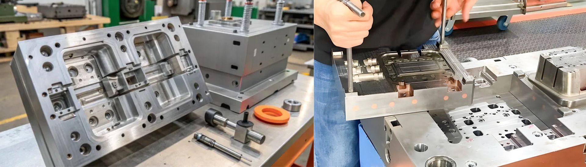
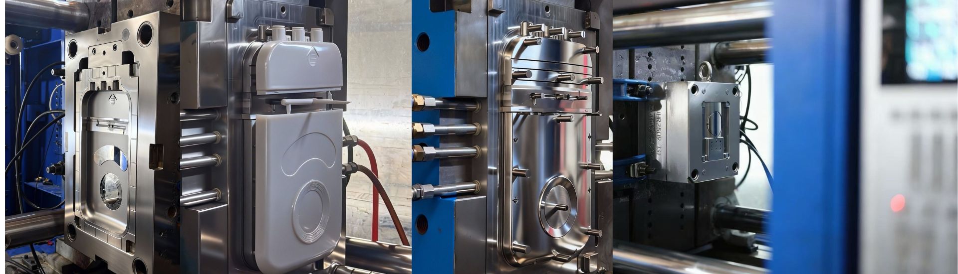
Draft is the slight taper added to every wall that runs parallel to the direction the mold opens. As the mold opens, the part must break free of the cavity walls on the outside and slide off the cores that form the inside. With zero draft, the part and the steel stay in full surface contact from the first millimeter of ejection, and friction does the rest: white stress marks, scuffed surfaces, bent ejector pins — or parts that will not release at all.
Draft works together with shrinkage. Plastic cools and contracts around cores, gripping them tighter than any CAD model suggests. That is why material selection and draft cannot be decided independently — the resin determines how much the part grips the steel.
One distinction worth remembering: external walls (formed by the cavity) release relatively easily because the part shrinks away from them. Internal walls (formed by cores) are the problem — shrinkage clamps the part onto the core. When you must choose, give internal surfaces more draft than external ones.
The Baseline Rule: 1 to 2 Degrees
If you remember nothing else from this article:
- 0.5° per side is the practical minimum — only for shallow parts (< 25 mm deep), polished surfaces, and easy-flowing resins.
- 1° per side is the default for most walls. Safe, invisible to the eye, and rarely questioned by any molder.
- 2° per side for deep parts (> 50 mm), textured surfaces, and anything with a long core.
Draft of 1–2° is not visually noticeable on most products. If a stylist objects, show them the same part rendered with and without it — nobody can tell the difference, but everyone can tell a scuffed part.
Recommended Draft Angles by Material
The table below lists working values for minimum draft per side on a polished mold. “Recommended” is what we ask for on new projects; “minimum” is where a molder will start arguing.
| Material | Minimum (polished, per side) | Recommended (per side) | Notes |
|---|---|---|---|
| PP (unfilled) | 0.5° | 1° | Slippery, low ejection force; tolerates the low end |
| HDPE / LDPE | 0.5° | 1° | Flexible, releases well |
| ABS | 0.5° | 1° | Predictable; standard housings work at 1° |
| PC / PC-ABS | 0.5° | 1–1.5° | Stiff, high ejection forces — avoid the minimum on deep walls |
| PA6 / PA66 (unfilled) | 0.5° | 1° | Shrinks hard onto cores; internal surfaces deserve 1.5° |
| POM (acetal) | 0.5° | 1° | Low friction helps, but high crystallinity grips cores |
| PMMA | 1° | 1.5° | Brittle and scratch-sensitive; scuffs easily on ejection |
| Glass-filled 20–30% (PA, PP, PBT) | 1° | 1.5–2° | Stiff, abrasive, high ejection load; low shrinkage gives less release help |
| TPE / TPU (soft) | 0.5° | 0.5–1° | Flexes off cores; undercuts sometimes survivable |
Two patterns sit behind the table. First, stiff, filled resins need more draft: glass fibers make the part rigid, so it cannot flex during ejection, and low shrinkage means it grips the core instead of pulling away. Second, soft materials get away with less: a TPE grip can literally peel itself off the steel.
Material also changes how much shrinkage works for or against you — the same physics covered in our plastic shrinkage rates guide. High-shrinkage PP pulls off cavities on its own; low-shrinkage filled PC stays put and demands draft and a well-placed ejection layout.
Draft Rules by Feature Type
Whole walls are the easy case. The expensive surprises live in features:
- Deep cores (H > 50 mm): 2° minimum, more if the surface will be textured. Deep, thin cores are also fragile — high ejection forces bend or crack them, so draft is protecting the mold as much as the part.
- Ribs: 0.5–1° per side. Remember that draft thickens a rib at its base; combined with a rib already at 60% of wall thickness, the root can exceed the sink-safe limit. Watch rib base thickness and draft together — our DFM checklist treats them as one item for exactly this reason.
- Bosses: 0.5–1° outside; deep, small-diameter bosses need 1–2° on the core that forms the bore.
- Holes: through-holes need 0.5–1° on their cores; deep holes (H > 2×D) need more, or they will scour on ejection.
- Slides and lifters: moving cores release sideways, so their formed surfaces technically need no draft — but every surface they shut off against does, or the seal leaks.
- Shut-off faces: keep these zero-draft and flat by design; do not let a global draft operation tilt them. A tilted shut-off either flashes or leaves a visible step.
Texture Costs Draft: The 0.025 mm Rule
Textured surfaces cannot slide against steel — the plastic mechanically interlocks with the etched pattern. The industry rule of thumb:
Add 1° of draft for every 0.025 mm (0.001 in) of texture depth.
So a light grain of 0.025 mm needs +1° on top of the base value, and a heavy leather grain of 0.1 mm needs +4°. This stacks on top of whatever the material table already asked for. Deep, textured parts in glass-filled resin routinely end up at 3–5° per side — which is why texture decisions belong in the DFM stage, not after the steel is cut. The steel grade also matters here: deeply etched patterns hold up best in fine-grain tool steels, one more input to the mold steel selection.
Skip the texture draft and the evidence appears within the first hours of T1: shiny pull marks where the grain was scuffed off, or parts hanging on the cavity until an operator with a pick finishes the ejection by hand.
How Much Draft Is That in Millimeters?
Draft angles are easier to judge in real dimensions. The offset per side is:
Offset (mm) = Depth (mm) × tan(angle)
Useful reference points:
- 1° over 25 mm of depth ≈ 0.44 mm per side
- 1° over 50 mm ≈ 0.87 mm per side
- 1° over 100 mm ≈ 1.75 mm per side
- 3° over 100 mm ≈ 5.24 mm per side
That last row is worth a pause: a deep, heavily textured 100 mm part gives up more than 10 mm across its width to draft. That is a real dimension on your drawing, and it must be priced in early — not discovered when the housing no longer matches the mating part.
Common Draft Mistakes That Cost Rework
- Drafting only the outside. Internal walls grip the core; they need at least as much draft as the outside, usually more.
- Adding texture without adding draft. The single most common cause of scuffed T1 parts.
- Drafting in the wrong direction. Draft must open toward the half of the mold the surface releases from. A wall drafted the wrong way turns into an undercut and forces a side action.
- Assuming “the molder will handle it.” Adding draft after steel is cut means welding and re-machining — cost and schedule the quote never included. Changing draft in CAD takes minutes; changing it in steel takes days.
- Zero-draft on vertical aesthetic walls. Sometimes a design genuinely demands near-zero draft. It is possible — with polished steel, easy-flow resin, and careful ejection — but it must be a deliberate, molder-agreed decision, not an accident.
How Draft Is Handled in a DFM Review
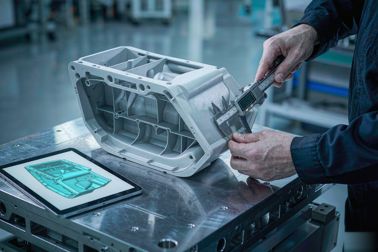
A proper DFM review treats draft as a system, not a number: material first (shrinkage and stiffness), then texture depth, then feature-by-feature draft on walls, ribs, bosses and holes, then ejection layout to match. The output is a short list: surfaces needing more draft, surfaces where a slide will be needed, and dimensions that will change visibly once draft is applied.
That review takes a day and costs nothing. Re-cutting steel because a textured deep core had 1° where it needed 3° typically costs weeks.
Get the Draft Right Before Steel Is Cut
Draft is a five-minute CAD edit and a multi-week mistake if missed. At D-TOP MOLD, every project starts with a free DFM review that checks draft by material, flags texture and deep-core requirements, and shows you exactly which walls will move and by how much — before any steel is ordered. We reply with a complete quote within 12 hours.
Send us your 3D files, and we will return a draft-by-material assessment with your quote.