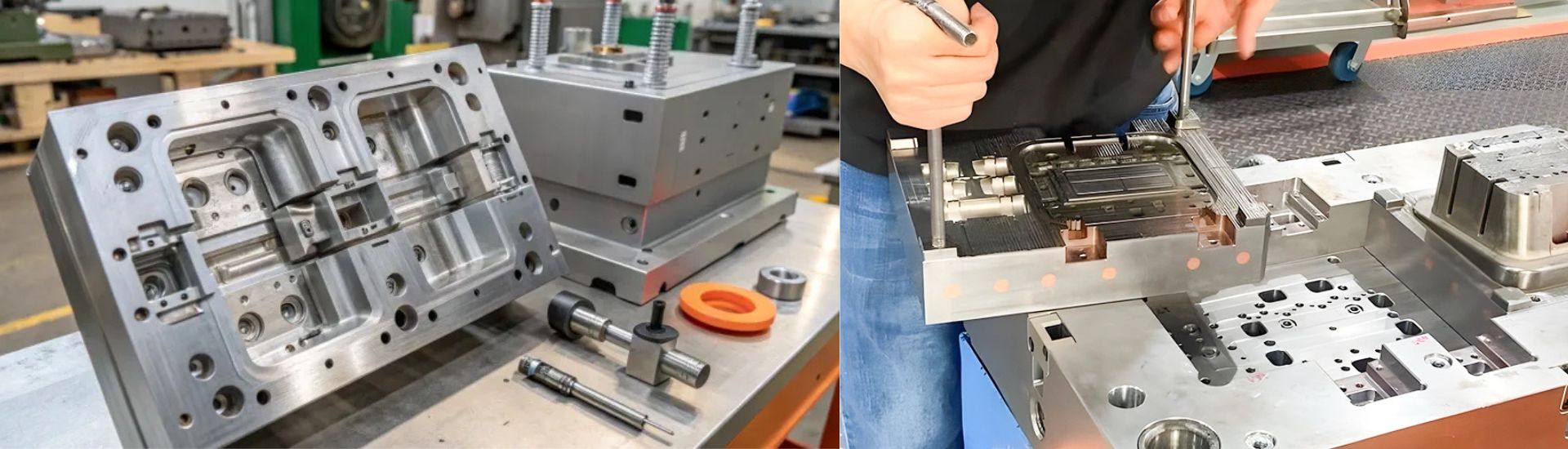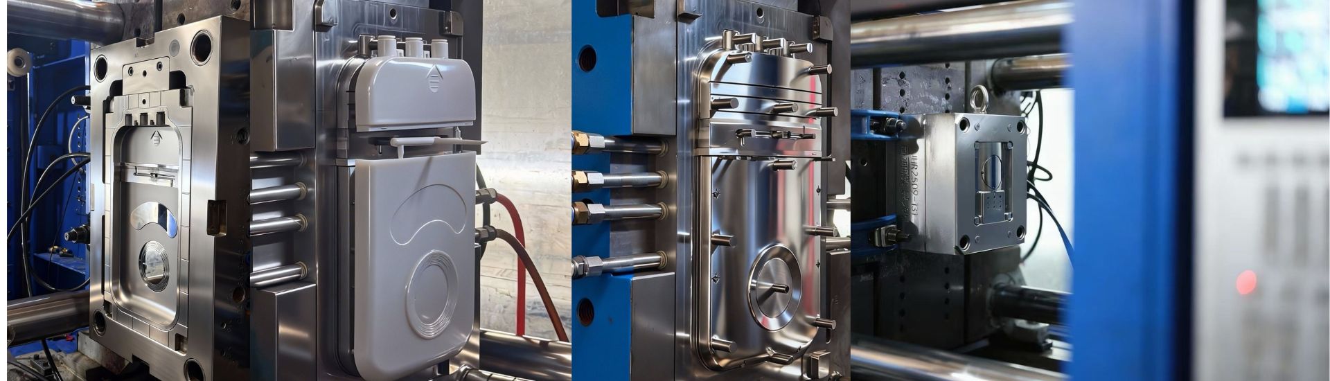


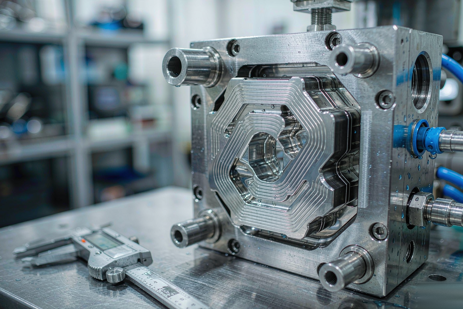
Cooling dominates the injection molding cycle. Depending on wall thickness and material, cooling accounts for roughly 50–70% of the time a part spends in the mold — yet for decades, toolmakers have cooled molds with straight drilled channels that can never follow the shape of the part. Conformal cooling changes that: cooling passages that curve around the cavity, staying a consistent distance from every wall. The result, on the right projects, is cycle time reductions of 20–40% and flatter, more stable parts.
The keyword is the right projects. Conformal cooling adds real cost to a mold, and on low-volume or simple parts it never pays back. This guide explains how it works, what it delivers, and — more importantly — how to judge whether it pays off for your part before you commit to the extra tooling cost.
What Conformal Cooling Actually Is
Conformal cooling is a mold cooling design in which the coolant channels follow the contour of the cavity surface at a near-constant distance, instead of running as straight drilled lines wherever a drill can physically reach.
In a conventional mold, deep or complex geometry forces compromises: cooling lines sit farther from thick sections, bend around ejector pins and sliders, or simply do not exist in corners where heat accumulates. In a conformal mold, the channels spiral, loop and weave with the part geometry — typically 8–15 mm below the steel surface, sized to keep the coolant velocity and heat extraction uniform across the whole cavity.
The channels themselves are usually produced by metal additive manufacturing — laser powder bed fusion (SLM/DMLS) printing of a mold insert in maraging or tool steel powder — then machined and polished on the working surfaces. The printed insert is fitted into a conventionally built mold frame, so only the thermally critical region carries the added cost.
Why Straight Drilled Lines Leave Money on the Table
Three problems with conventional cooling show up directly on your invoice:
- Uneven wall distance. Where a drilled line passes 10 mm from the cavity in one spot and 40 mm in another, those areas cool at very different rates. The slow spots set the cycle time; everything else is over-cooled.
- Hot spots in corners and cores. Deep cores and internal corners are hard to drill. They stay hot shot after shot, stretching cooling time and driving differential shrinkage — a root cause of the warpage and sink defects that show up in T1 dimensional reports.
- Cooling limits thin-wall economics. On high-volume packaging, closure and thin-wall work, every second of cooling time multiplied by millions of shots is the part price.
Conformal channels attack all three: uniform distance means uniform cooling, and uniform cooling means the slowest spot stops being the bottleneck.
The Payoff: Cycle Time Reduction
Published case studies and supplier data consistently report cooling-time reductions of 20–40% when switching a thermally limited part from drilled to conformal cooling, with total cycle time typically improving 15–30%. The exact number depends on how cooling-limited the part was to begin with.
| Scenario | Typical Cycle Time Gain | Why |
|---|---|---|
| Thick-section part, cooling-dominated cycle (PP, HDPE) | 25–40% | Heat extraction was the bottleneck; uniform channels shorten it directly |
| Part with deep cores / internal corners | 20–35% | Hot spots eliminated; differential shrinkage drops |
| Thin-wall, high-cavitation part | 10–20% | Cycle already short; every 0.5 s scales across huge volumes |
| Technical part limited by filling, handling or automation | 0–10% | Cooling is not the bottleneck — conformal cooling cannot help what it does not limit |
That last row is the one buyers overlook. If your cycle is dominated by robot take-out, assembly line speed or filling constraints, perfecting the cooling buys you nothing.
The Quality Payoff: Warpage and Dimensional Stability
Cycle time is only half the story. Uneven cooling creates uneven shrinkage, and uneven shrinkage creates warp. Flat parts go banana; holes go out of round; faces crown.
Because conformal cooling equalizes the temperature across the cavity, parts shrink more uniformly. On glass-filled and semi-crystalline resins — where shrinkage is already directional and thickness-sensitive — this often matters more than the cycle time itself. Molders report flatter T1 parts, fewer steel-adjustment loops, and less need for post-mold fixtures. On tight-tolerance programs, that can shorten the whole tooling validation timeline by removing one or two rework iterations from the tooling lead time.
When It Pays Off: The Business Case
Run your project through this checklist. The more boxes you tick, the stronger the case:
- High annual volume. Rule of thumb: above roughly 100,000–300,000 shots per year, a 15–30% cycle reduction pays back the added tooling cost within months. Below 20,000 shots per year, rarely.
- Cooling-limited cycle. If wall thickness and resin dictate that cooling sets the pace (check the moldflow analysis), the gain is real.
- Warpage is the open risk. Flat, asymmetric or tight-tolerance parts where cooling uniformity directly protects scrap rates and CPK.
- Thick or variable wall sections. Bosses, ribs and deep cores that drilled lines cannot reach effectively.
- Part price is cooling-price. Packaging, closures, consumer housings — anywhere a half-second per shot is quoted into every unit for years.
- Expected program life. A mold that runs 5+ years amortizes the insert cost; a 6-month prototype program does not.
When It Does NOT Pay Off
Be honest with yourself here — a good molder will be:
- Low volumes. A 5,000-shot program cannot amortize the insert. Conventional cooling plus a slightly longer cycle is cheaper by far.
- Simple geometry with even walls. A flat, uniform part is already cooled efficiently by drilled lines.
- Amorphous resins, generous tolerances. ABS housings with ±0.3 mm tolerances rarely need the thermal uniformity.
- Cycle limited by something else. Automation, insert loading or degating set the pace — cooling gains disappear into waiting time.
- Tight tooling budget and schedule. The printed insert adds cost and lead time to the tool build.
What It Adds to the Tool Quote
Conformal cooling is priced as engineered add-on work, typically on the inserts that carry the cavity or core:
- Insert cost: printed steel inserts commonly add roughly 20–40% to the cost of the affected core/cavity set versus conventional machining.
- Engineering: thermal simulation (moldflow cooling analysis) and channel routing design — necessary, not optional.
- Peripheral equipment: conformal channels have smaller diameters and longer paths, so temperature-controlled water units and good filtration matter more than on drilled molds.
- Maintenance: channels can scale and clog like any water line; printed inserts need the same water treatment discipline, and repairs are less routine than drilling and plugging a straight line.
On a mid-size production mold, the total tool cost premium typically lands in the 10–25% range — highly dependent on how much of the tool needs printed inserts. Get the premium quantified against your actual volumes in a cycle-cost comparison before deciding; the arithmetic is simple: (cycle time saved × annual shots × machine rate) vs. added tooling cost.
How the Inserts Are Made
A brief buyer’s tour of the manufacturing route, so quotes make sense:
- Thermal simulation first. Moldflow cooling analysis locates the hot spots and defines where channels are needed — and where they are not.
- Channel design. Diameters typically 6–10 mm with smooth internal bends; distance-to-surface and pitch are engineered per region, not guessed.
- Printing. Laser powder bed fusion in tool steel powder (maraging steel grades such as 18Ni300 are common), build orientation and supports chosen to protect channel integrity.
- Finishing. Heat treatment, machining of interfaces and working surfaces, polishing; the insert is then fitted into the conventionally machined mold frame.
- Leak and flow testing. Every circuit pressure-tested before the tool ships.
Steel choice for the rest of the tool follows the same logic as any production mold — our injection mold steel selection guide covers the grades.
Questions to Ask Before You Pay for It
- Is my cycle actually cooling-limited? Show me the moldflow cooling analysis.
- Which inserts would be printed, and what exactly does that add to the quote?
- What cycle time reduction do you commit to — and will the T1 report verify it?
- How are the circuits plumbed, and what water treatment does the tool need?
- What is the payback at my annual volume — show me the calculation.
A supplier who answers with numbers instead of enthusiasm is the one to buy from.
Get the Cooling Strategy Right Before You Buy the Mold
Conformal cooling is a sharp tool — excellent on the right job, wasted money on the wrong one. At D-TOP MOLD, every quote starts with a free DFM review: we check whether your cycle is cooling-limited, model the thermal behavior, and tell you honestly whether conformal inserts pay back at your volumes. Expect a complete quotation within 12 hours.
Send us your 3D files and annual volume — we will show you the cooling math before you spend a cent on steel.