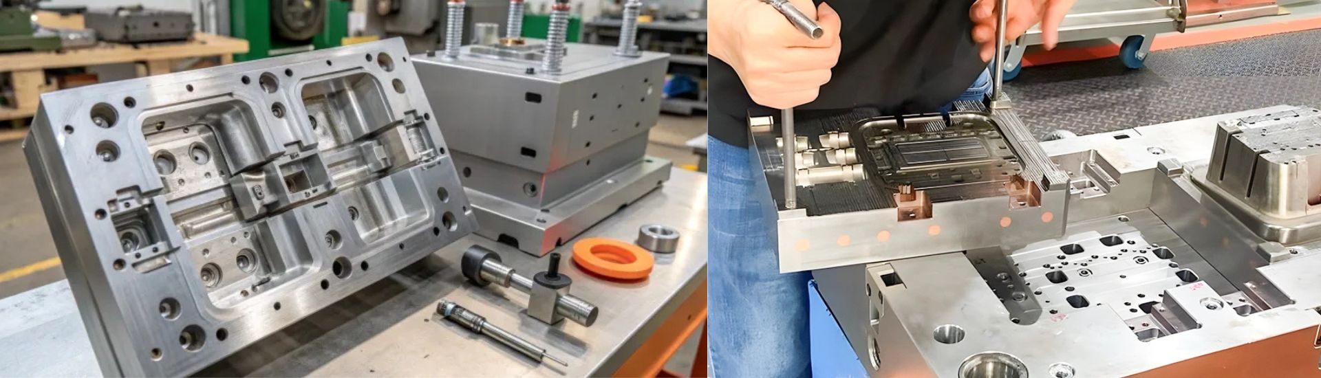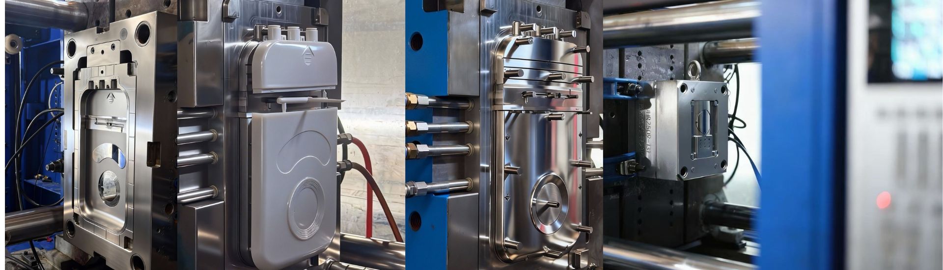


Every injection mold is a bet on a part design. If the design fights the process, the bet loses — in sunk steel, in weeks of rework, in field returns. The cheapest place to fix a problem on an injection molded part is on the 3D model, before any steel is cut. A DFM (Design for Manufacturability) review is what stands between a clean T1 sample and a six-month project that never quite settles down.
This 2026 checklist distills the seven design rules we flag on most RFQs that come through our Suzhou facility. Apply them to every part before you release a 3D model for tooling, and you will cut the most expensive sources of rework — sink marks, warpage, short shots, weld lines, and difficult ejection — out of the project before the first steel is cut.
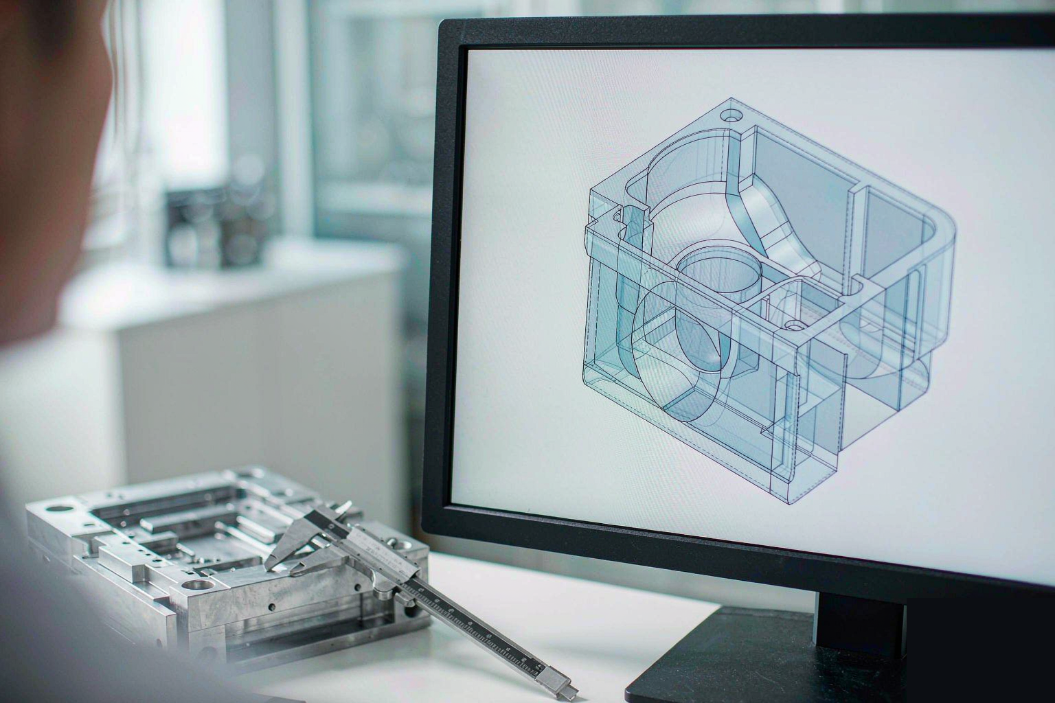
Why DFM Pays for Itself Before Steel
A change on the 3D model costs minutes. A change on a hardened, polished injection mold costs thousands of dollars and two to three weeks of cycle time. The math behind a free DFM review is straightforward: for every dollar spent preventing a tooling issue at the design stage, you save between five and twenty dollars in corrective work later. Most rework we see on production parts traces back to one of three things — uneven wall thickness, missing or wrong draft, or a gate in the wrong place — and all three are visible on a STEP or IGES file long before the mold is built.
1. Keep Wall Thickness Uniform (2.5–3.5 mm Target)
Why it matters. Wall thickness is the single biggest driver of cosmetic and dimensional defects on an injection molded part. When two sections of a part have different thicknesses, the thicker section stays molten longer than the thinner one, and the differential shrinkage pulls the surface down. The result is a sink mark above the thick area, a void inside it, or a warp as the part cools unevenly.
DFM rule. Keep wall thickness in the 2.5–3.5 mm range whenever the function allows. When a thick section is unavoidable, do not transition to it with a sharp step — use a smooth 3:1 to 5:1 taper so the material can pack and cool evenly. The classic rib rule also belongs here: ribs should be 50–70% of the nominal wall, never equal to it, otherwise the rib becomes a wall and the geometry reverts to the original sink problem.
2. Add Real Draft Angles (0.5°–1° per Side Minimum)
Why it matters. The molded part has to come out of the cavity. If the sidewalls have no draft, the part will drag on the steel as it ejects, leaving scuff marks, dimensional drift, or — in the worst case — a stuck part that takes the ejector pins with it. Draft is the angle added to every wall that is parallel to the mold opening direction.
DFM rule. Use 0.5° to 1° draft per side on every depth. Go to 1°–2° for parts deeper than 50 mm, for textured surfaces (add 1° per 0.025 mm of texture depth), and for glass-filled or abrasive materials like PA66-GF. Draft is essentially free at the design stage and very expensive to add after a tool is cut — it usually means welding the cavity and re-cutting the wall.
3. Design Ribs and Bosses Around the Part Wall
Why it matters. Ribs add stiffness without adding mass, and bosses accept screws and fasteners. But a rib that is the same thickness as the wall creates exactly the sink problem in rule #1. A rib with sharp internal corners creates a stress riser that will crack under load, especially with glass-filled materials.
DFM rule. Keep rib thickness at 50–70% of the nominal wall, with a fillet of 0.25–0.5× the wall thickness at the base of every rib. Add a 0.5°–1° draft on the rib sidewalls, in the same direction as the cavity draft. For bosses, follow the same 50–70% rule for the boss OD relative to the wall, and never put a boss on a flat surface without a fillet at the base. Where a rib meets a wall, allow the rib to “core out” the opposite wall by being slightly thinner — this breaks the symmetrical cooling that causes warp on flat plates and is one of the cheapest geometry changes in the entire DFM toolkit.
4. Place Gates in Non-Cosmetic, Non-Structural Areas
Why it matters. The gate is where the molten plastic enters the cavity, and the spot where it lands almost always carries a witness — a small dimple, a faint halo, or a vestige that needs to be trimmed. Weld lines also form downstream of any feature the melt has to flow around, so the gate position determines where weld lines form too.
DFM rule. Locate gates on non-visible, non-load-bearing surfaces whenever possible. Put the gate on the inside of a housing, on a thick boss, or on a designated witness surface that will be hidden under a label. For multi-cavity tools, balance runner lengths so all cavities fill in the same time window, otherwise the shortest runner fills first and over-packs while the longest runner short-shots. For parts where the gate is a visible cosmetic feature (closures, lenses, medical disposables), specify a hot runner with a valve gate, or plan for a sub-gate or tunnel gate that can be auto-degated — both decisions affect steel layout, runner layout, and cost, and belong in the RFQ, not in the T0 conversation.
5. Use the Real Material Shrinkage, Not a Guess
Why it matters. Plastic shrinks as it cools, and the shrinkage factor is what turns a cavity dimension into a part dimension. A 0.5% error in shrinkage is a 0.5% error in every dimension of the part. Generic shrinkage values from a chart are usually wrong for filled materials, glass-reinforced resins, and any material processed outside its standard window.
DFM rule. Get the actual shrinkage from the material supplier’s data sheet for the specific grade you are using, at the processing conditions you intend to run. For glass-filled materials, expect anisotropic shrinkage — the part will shrink more across the flow than along it, and that anisotropy must be built into the cavity. For semi-crystalline materials (PP, PA, POM), expect higher shrinkage and a wider processing window. For amorphous materials (PC, ABS, PMMA), expect lower and more uniform shrinkage. For tight-tolerance parts, machine the cavity undersize by 0.2–0.3% and trim the final dimension with a steel-safe shim after the first article inspection — much cheaper than scrapping a cavity block.
6. Fillet Every Internal Corner (0.25× Wall Minimum)
Why it matters. Sharp internal corners on an injection molded part are three problems at once: a stress concentration that will crack under cyclic load, a flow restriction that traps air and causes burn marks, and a sink-prone geometry because the material at the corner is the last to pack.
DFM rule. Add a fillet of at least 0.25× the wall thickness to every internal corner. For glass-filled or impact-resistant parts, go to 0.5× wall. External corners can stay sharp (or get a small chamfer) — it is the internal corner that matters for both flow and strength. Zoom in on every internal corner in your CAD model: if the radius is below 0.5 mm on a 2.5 mm wall, the corner is too sharp. Bump it before the RFQ and you will eliminate most of the corner-sink and corner-crack tickets that come back from the field.
7. Specify Only the Tolerances You Will Inspect
Why it matters. Every tolerance on a drawing is a promise your mold maker has to keep. A general ±0.1 mm tolerance on a 300 mm housing is realistic; ±0.05 mm on the same part is not, and the cost of holding it shows up in steel selection, EDM time, polishing, and inspection. Over-specified tolerances are one of the most common ways a tooling budget doubles without anyone noticing.
DFM rule. Use the manufacturer-default tolerance (typically ±0.2 mm for the first article, ±0.1 mm after process capability is proven) on every dimension that is not a critical interface. Call out tight tolerances only on the features that mate to other components — and when you do, also call out the datum scheme and the GD&T frame. A note that says “critical” on a drawing is not a tolerance; it is a hope. Tightening a single dimension from ±0.1 mm to ±0.05 mm on a 4-cavity mold can add 8–15% to the mold cost and push T1 by a week — apply that across a drawing with 30 “critical” notes, and the project is no longer the project you quoted.
Quick Reference Table
| Rule | Target | Common violation | Where to fix it |
|---|---|---|---|
| Wall thickness | 2.5–3.5 mm, uniform | Thick boss next to thin wall | 3D model, DFM review |
| Draft angle | 0.5°–1° per side | Vertical walls, no draft | 3D model, RFQ stage |
| Ribs / bosses | 50–70% of wall, filleted | Ribs equal to wall, sharp base | 3D model, DFM review |
| Gate location | Non-cosmetic, non-structural | Gate on visible face, weld on load path | RFQ + mold-flow analysis |
| Shrinkage | Material-specific, anisotropic for GF | Generic chart value, isotropic assumption | Material data sheet + cavity design |
| Internal corners | 0.25–0.5× wall fillet | Sharp internal corner < 0.3 mm | 3D model, FEA review |
| Tolerances | Default ±0.1–0.2 mm, tight only where mated | “Critical” notes without GD&T | Drawing review at RFQ |
How to Apply This Checklist on Your Next Project
The seven rules above are the same checks our engineering team runs on every RFQ that comes through, in the same order, in about four hours of work. To apply them on your own part:
- Open the 3D model in your CAD tool and check wall thickness with a section view at every feature transition.
- Run a draft analysis on every wall parallel to the mold opening direction.
- Mark the proposed gate location on the model and trace the weld-line path that will form downstream of any hole or insert.
- Pull the actual shrinkage value from the resin supplier’s data sheet for the specific grade and processing window.
- Inspect every internal corner radius in the model and flag anything under 0.5 mm for review.
- Audit your drawing for “critical” notes and replace each one with a real GD&T frame and a datum scheme.
If you are about to start a new injection mold project, send us your STEP or IGES file and your target annual volume. D-top Mould provides a free DFM review and a 12-hour quote response on working days — built in our Suzhou facility with P20 / H13 / S136 steel, hot runner systems from Mold-Masters and Yudo, and English-speaking project management from RFQ through T1 sample approval. We flag the wall-thickness, draft, gate, under-cut, and tolerance issues that turn into sink marks, weld lines, and short shots before the steel is cut.
Upload your 3D model on the Quick Quote page and you will have a real, fixed quote — with DFM notes you can act on — by the next business day.